Hier klicken, um den Inhalt von YouTube anzuzeigen.
Learn more in YouTube’s privacy policy.
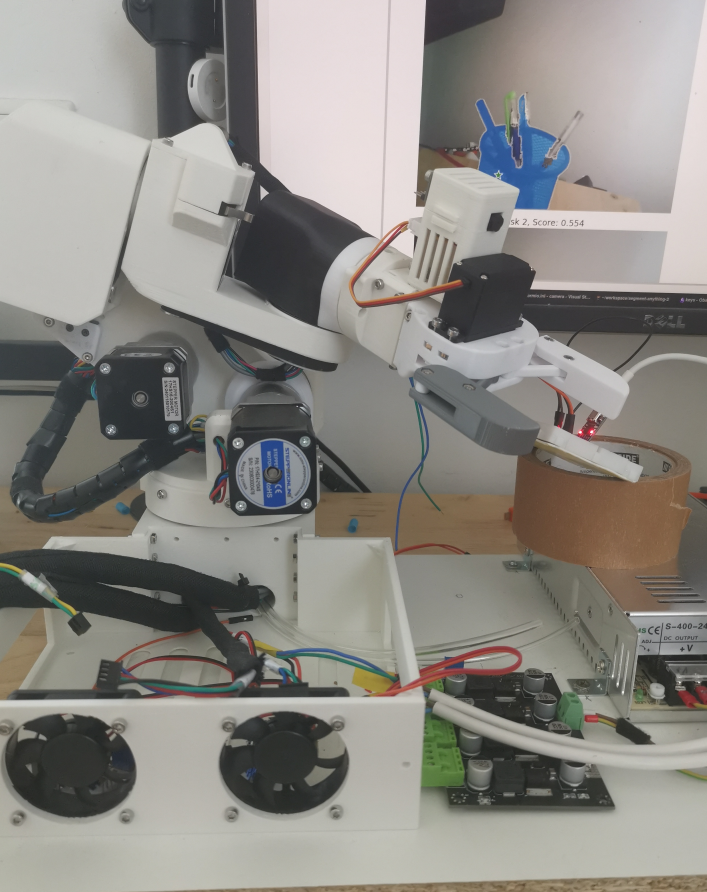
Discovered a timing issue when using the esp32-camera. The error indication is simple: with certain camera configuration, esp_camera_fb_get returns null_ptr. This is definitely a timing mismatch in the hardware and controller code. As far as I can see, the hardware is supposed to check the camera status and fill in the frame buffers in the PSRAM in an ISR in some constant frequency (related to config.xclk_freq_hz) and I fetch (and return) the frame buffer in the working loop. If one side is too slow or too fast, there will be no enough / too much events and the working queue became empty or full, etc.
I got some working combinations after quite some trial and error.
xclk_freq_hz | frame_size | jpeg_quality |
| 8 | FRAMESIZE_VGA | 12 |
| 12 | FRAMESIZE_VGA | 2 |
| 16 | FRAMESIZE_QQVGA | 12 |

BQTT Manta board has 1 and only 1 slot for inductive proximity sensors. In my case, I will need 3 in all. So I am scratching the head a lot for any workarounds.
Firstly, there is a very good introduction of PNP/NPN sensors https://www.balluff.com/de-de/blog/wie-unterscheidet-sich-der-anschluss-von-sensoren-mit-pnp-und-npn-ausgang. I started to verify my NPN ones at my hands. I plugged the brown(+) and blue(-) pins to the fan slot, leaving the signal (black) pin unattached. The signal pin delivers high (12V) when the sensor inactive and turn to low (0V) when the sensor is activated. Ideally, I wish I could simply use it as the signal pin and plug into the signal pin of the endstop slots. But what I know the slot should take a 5V input instead of 12V. So there is a risk of frying the board.
One option is to use Voltage divider. I did get a 5V signal in this way. But I came to another observation of the board that the signal pin of the endstop slot is normally at the 2.8V level. It means it stays at high usually, and feed a 5V signal remains high. If it was PNP sensor, probably things would just work.
Is there a way to reverse its way, 5V when inactive and 0V when active?
Unlikely without some complex circuits. But inspired by this thread, I’ve got a brainwave. Wire a diode 1N4007 reversely between the endstop and the sensor! When sensor inactive, the diode stops the current from the sensor side, and the endstop remains at 2.8V. When the sensor activated, the diode let the current flow through and endstop connects to the ground, it becomes 0 now. In this way, it detected the target signal.
© 2026 Folding recursively
Theme by Anders Noren — Up ↑